
Here’s what I come up with for sawtooth signal for the scope.
I took the ramp generator circuit from learningaboutelectronics.com
It uses 3/4 Op Amps from the LM324 chip. I tested the circuit from learningaboutcelectronics.com and it works in multisim. S1 and R8 controls the frequency. R6 controls the amplitude of the sawtooth voltage. When you change the frequency the output voltage changes as well, so having a non-inverting amplifer helps. XFG1 and XSC1 are testing tools and only needed for testing. Another thing to save money I put some of capacitors in series to lower capacitance. Also there is two 10k resistors in parallel to make 5k so you could use 4.7k-5.1k or ones from your minimum order of 10k. I decided to use a Darlington Power transistor because of its high gain. When changing one pot, you may need to change the other one. NOTE I ONLY SIMULATED IT IN MULTISIM, I WILL BUY THE PARTS SOON AND TRY IT IN REAL LIFE.
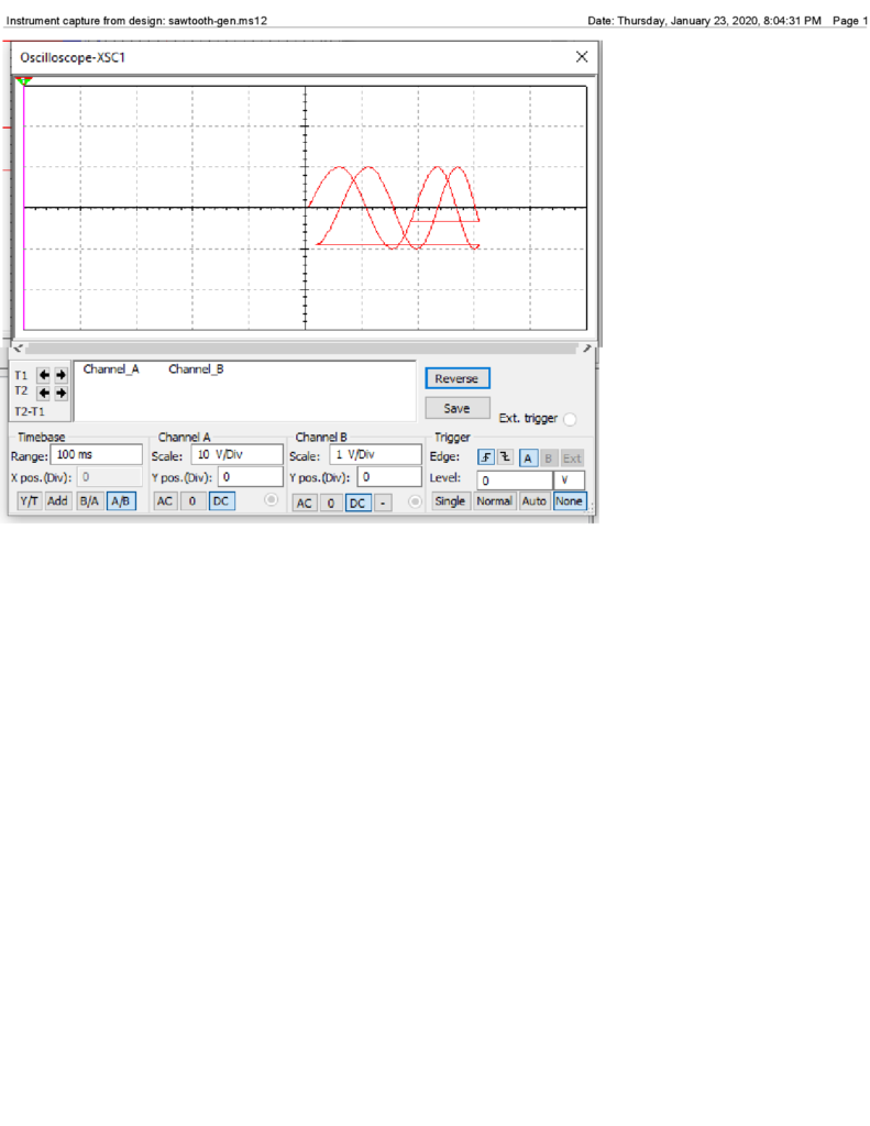
Sine wave test 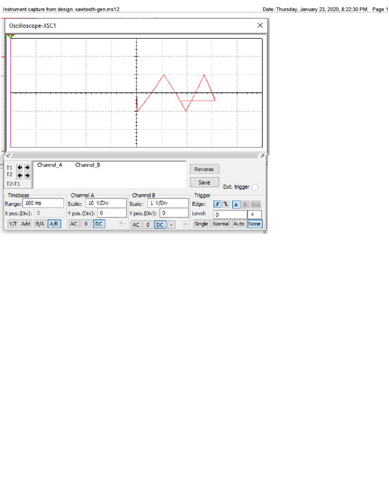
Triangle wave test 
Circuit diagram
