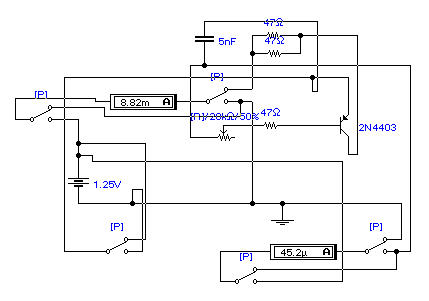
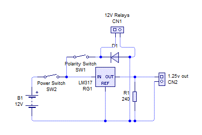
This is the simplest in circuit transistor tester. It uses two ammeters to measure the transistor gain. It is kinda like the heathkit IT-18 one but uses 2 meters instead of one. I plan on using relays for the polarity switch instead of a 5PDT Rotary switch. It uses a LM317 regulator for providing a very low voltage(around 1.25v). This will prevent turning on anything on and interfering with the gain measurements. The capacitor is to remove oscillations. I used two 8 cent 10nF capacitors in series to make 5nF. All [P] switches are all part of the polarity relays. I need a 4pdt relay and a spdt relay used to provide the 5pdt switch.

How do I measure the gain?
The gain is simply
$$hFE=\frac{I_c}{I_b}$$
Where hFE is your gain, Ic is your collector current and Ib is your base current I did the math with the transistor in the circuit diagram and got around 195.


The collector meter is 50mA and base meter is 100uA
A video will soon come when the parts come in the mail
