
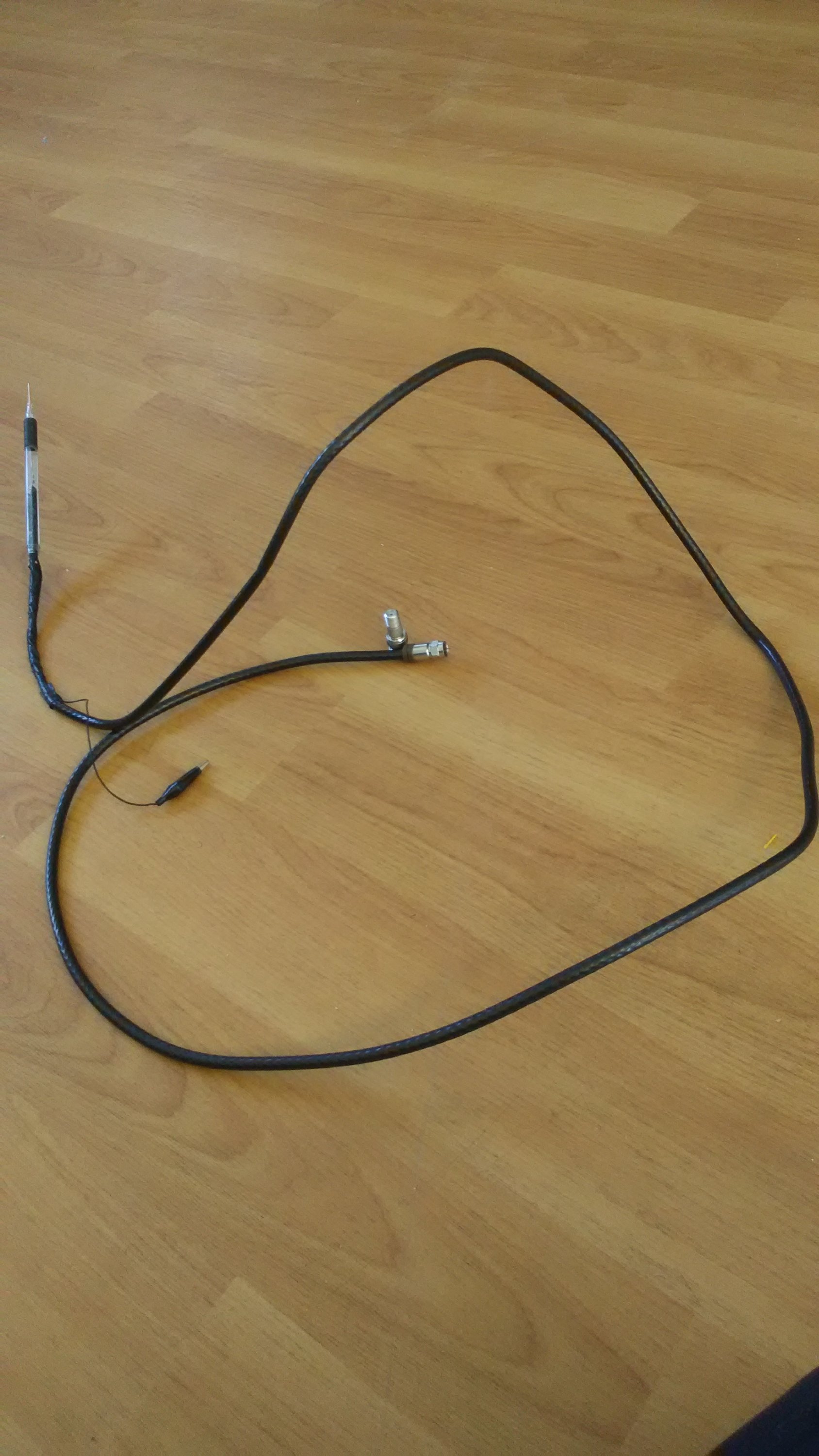
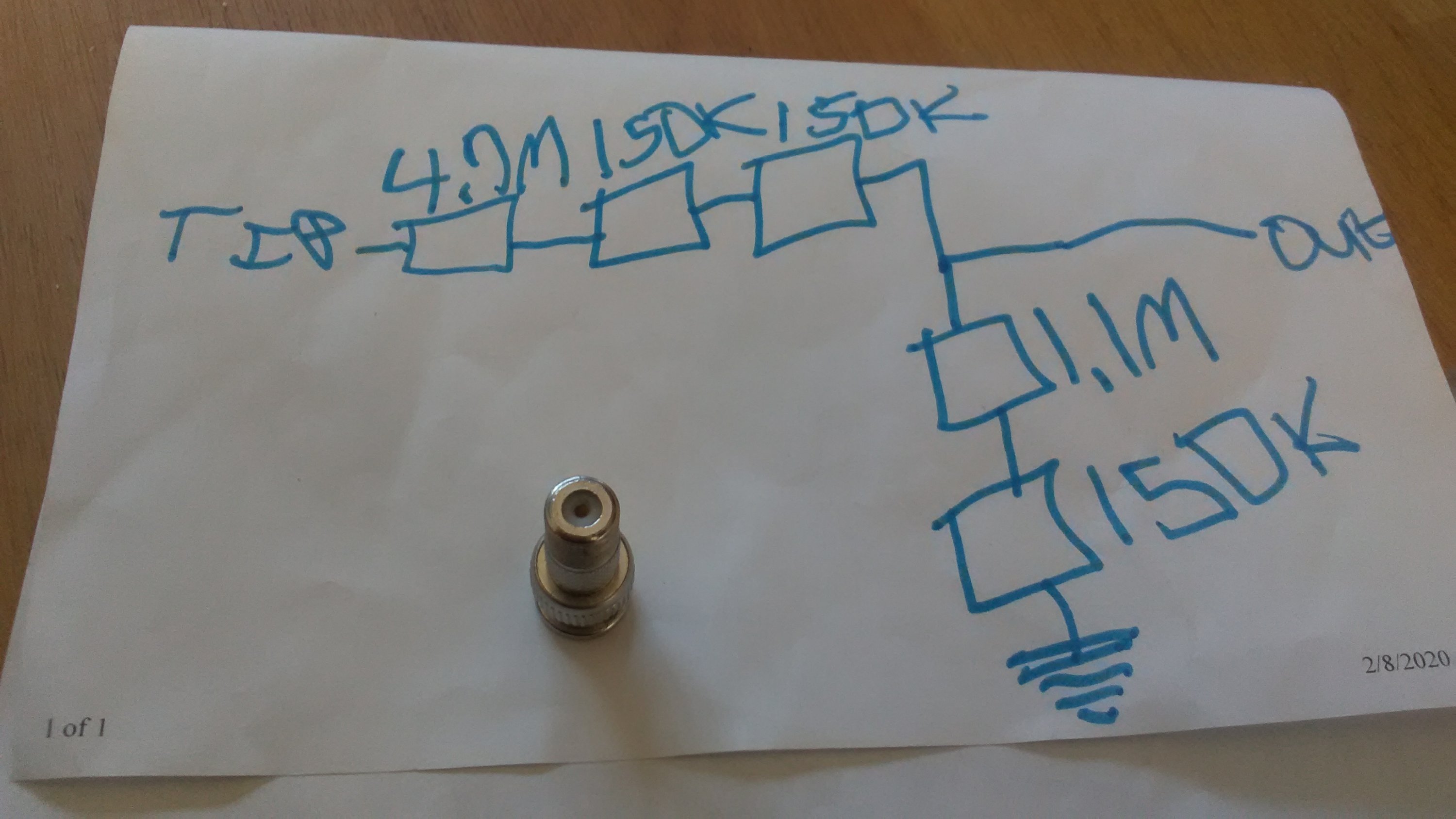
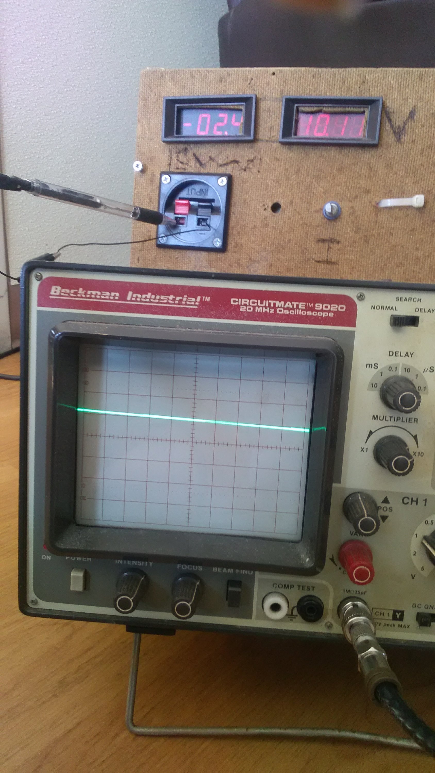
In this blog post I will show you how to build a x1 probe and a x10 probe. You will need resistors, a pen(prefer one with the tip can come off),6ft or less of TV coax, paper clip,one alligator clip, 1 Meg impedance oscilloscope and a f jack to BNC adapter. You will want to get the lowest wattage resistors. This is so that it can be easier to put the resistors inside of the pen. The resistor closest to the tip is should be 5 Meg, and the one that connects to center and ground is 1.25 Meg. When connected to the 1 Meg oscilloscope it makes a divide by 10. And that is how this times ten probe works! The times one is the simplest, you just hook tip and ground directly to the oscilloscope. Also you want the lowest amount of wire exposed. In the picture of the oscilloscope shows 10.11vdc being measured on 1v/div. It definitely reads approximately 1v. You might be asking why use F-jack coax? Here’s what it says on Wikipedia about it:
The F connector is an inexpensive, gendered, threaded, compression connector for radio frequency signals. It has good 75 Ω impedance match for frequencies well over 1 GHz[2] and has usable bandwidth up to several GHz.
Making the x10 probe
- Cut one end of the cord, make sure the piece you are using is 6 foot or less
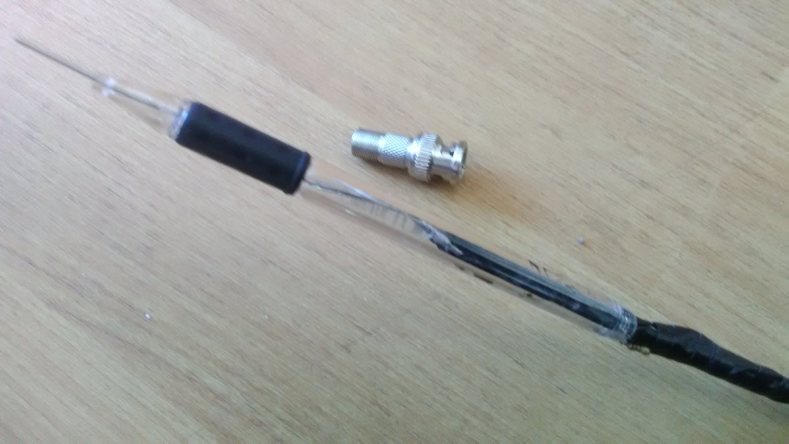
- Strip the coax back far enough that the cord can fit threw the pen, and some for the ground clip. Strip half a inch of the insulator off for access to the center pin.
- Here comes the hard part, soldering the resistors. Solder the 150k resistor to the braid. Make sure not to melt the insulator separating the center pin from ground. Make sure to make connections short to prevent interference.
- Next solder the 1.1Meg resistor to the 150k resistor from step 3 to the center pin. Again make sure to use short connections as possible.
- Solder the next 2 150k resistors in series with a 4.7Meg at the end.
- next solder the 4.7meg to the paper clip, Bend the paperclip all the way back before soldering.
- Carefully push the probe into the pen. Clip off excess paperclip. And that’s it!
Making the x1
- Cut 6 foot or less of the coax.
- Strip the coax back enough for the pen fit on the cord. Strip an inch on the center insulator.
- Push the cord threw the pen and cut off excess wire from the tip and your done!
Testing the x10 probe
You will need a multimeter and a power source (isolated power supply, battery,etc)
- First measure the resistance between ground and center, you should get 1.25 Meg. Not close to zero or open.
- Next measure from the ground clip and the probe tip, you should get 6.25 Meg. This is because the top resistor is in series with the bottom one and there resistance adds up.
- Now if your meter is 1 Meg impedance then you can connect your probe up to a power source and measure it to see if it equals it divided by 10. If not then measure it on the oscilloscope. Make sure that if it’s DC your coupling is not AC as it blocks DC.
Also it might be possible to make a x10 resistor probe for 10 Meg impedance just change the resistor that connects to the tip to 50 Meg and and the one between it and ground to 12.5 Meg. I had to adjust the VAR knob on the scope to calibrate it to the correct measurement

Hi my loved one! I want to say that this post is amazing, nice written and include approximately all
significant infos. I would like to look more posts like this
.
Asking questions are genuinely nice thing if you are not understanding something totally, however
this piece of writing gives good understanding yet.