
This tester is pretty simple and cheap to build. All you need is
- 2x RJ45 Female connectors(like the ones for putting into the wall)
- 4x 2-pin Bi-color LEDs
- 4x 150 ohm resistor
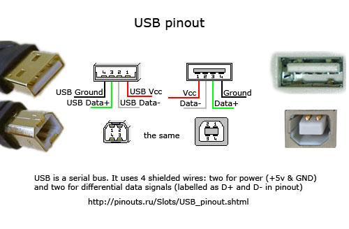
- USB A Male Connector(I cut a USB Cord)
- 4x DPST or DPDT Switches
- A PCB Or floor tile and copper tape
- Some wire.
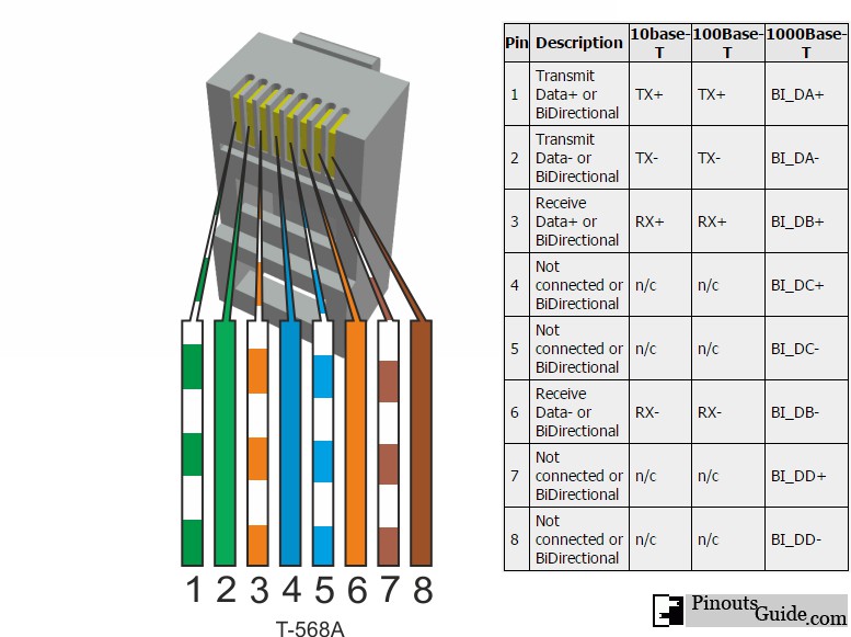
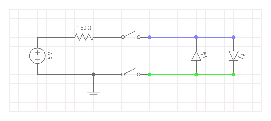
First cut and strip the USB Cord so that red and black wires are available to solder. Solder the white wire of the pair to the negative end of the switch and the solid color goes to the positive end of the switch like shown in the circuit diagram. The red wire will be connected to the resistor and the other end of the resistor is common + for the switches(solid color). The black is the ground for the switch(white wire of the pair). See figure 1 for RJ45 twisted pairs colors, include all 8 pins including the not connected.
To use simply turn one switch at a time to test the polarity of the twisted pair. Checkout the table below for test results.
| Twisted Pair | Straight-through | Crossover | Rollover |
|---|---|---|---|
| 1 and 2 | Positive 1 and 2 | Positive 3 and 6 | Negative 7 and 8 |
| 3 and 6 | Positive 3 and 6 | Positive 1 and 2 | Negative 3 and 6 |
| 4 and 5 | Positive 4 and 5 | Positive 7 and 8(1Gbps) or positive 4 and 5 | Negative 4 and 5 |
| 7 and 8 | Positive 7 and 8 | Positive 4 and 5(1Gbps) or positive 7 or 8 | Negative 1 and 2 |
The bold results are not needed for 10/100Mbps connection. Of course you could use a arduino,counter chips or flip flops. But that wouldn’t be the simplest tester.
