Clockwire Parallel Port Binary and Digital controlled clock

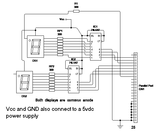
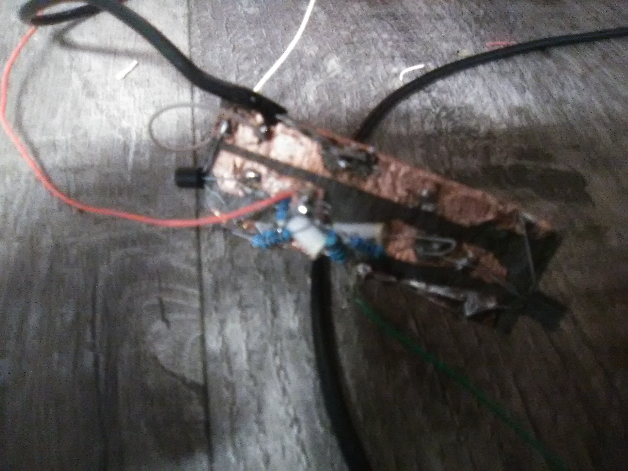
This program allows you to wire up a 2-digit Binary clock, Digital clock or both. It uses inpout32.dll file to output the time on the data register. I used a rj45 to db25 male module to make connection to my parallel port and the clock. There are 8 wires (9 if you want the hour and minute indicator). RJ45 has 8-pins so it works.

System Requirements

Windows 2000 or higher (32-bit Windows recommended)

A parallel port that supports the registers (most USB adaptors do not support it, they only support printers)

Elevens Solitaire

ScreenShot

This game is a work of art! The rules are simple, in fact it may even be easier to win than regular solitaire! The object of this game is to discard all the cards by taking a pair of 2 cards and adding them up to 11. Jacks, queens and kings are only discarded when there is only one of each visible they are discarded automatically. It has a Cheat-sheet feature that shows all combinations that can be made. You can either drag and drop cards or type in there number. There number is the # on each card. For example in this screenshot to discard the 7 of clubs and the 4 of clubs type 23. The source code is written in Delphi.

Resistor RJ45 Tester

This is a simple network cord tester that uses just 8 unique resistors. The values/wattage doesn’t matter as long as the meter can read them. They should be in the kiloohm range. I have made an Excel spreadsheet file that you can enter all 8 of the resistors and get the total parallel resistance. The pins are listed as binary 1s and 0s. J1 and J2 are the RJ45 connectors. I even entered the ones I’m using. It doesn’t tell you if it’s a patch cord, crossover or rollover, but tells you if the pins used on the cord are making connection. To tell what type of cord it is just look at the 2 ends.

Loader Loading…
EAD Logo Taking too long?

Reload Reload document
| Open Open in new tab

Basketball pump signal injector

This is a simple signal injector that can fit inside a mini basketball pump it requires:

  • 1x dc blocking capacitor(10nF to 10uF) C3(2.2uF Axiel Film Capacitor)
  • 2x 100nF Capacitors C1 and C2
  • 2x 1k ohm resistors R1 and R2
  • 2x 4.7k ohm resistors R3 and R4
  • 2x General Purpose NPN low power transistors Q1 and Q2(I used PN2222A)
  • A 1.2 to 14v dc power source
  • A alligator ground clip

This signal injector can come in handy for repairing radios, amplifers and old TVs and also square wave generator in a probe. Later on I will make a version that uses C1 and C2 as 470nF and R3 and R4 as 1 Megaohm and C3 as 47uF(Since the frequency is ultralow).

The specs

Where R=R2 or R3, C=C1 or C2 and \(C_{3}\)=C3

Frequency: \(f=\frac{1}{1.38RC}=1.5kHz\)

Output AC Resistance: \(X_{C3}=\frac{1}{2\pi*fC_{3}}\)

PCB Files

Christmas Light Contest 2023

This contest is to show your christmas decorations you put up this year. There is no prize but its just to show your christmas sprite. Voting ends 12/31/2023 and posting 12/25/2023. Note you can only vote once

Finished since 128 days, 5 hours and 37 minutes.

Simplest Wire Tracer/Coax Tester

This is a simple wire tester all you need is a 12-1000vac non-contact voltage detector. The ideal is to connect AC live wire to the red circle is. You do not use ground or neutral wires, these wires should be cut off. If the cord is shielded(coax) the detector doesn’t. Even though there’s only one wire used you should not touch the wire. The 5v is actually the ac mains voltage. The three switches choose 1 out of 8 outputs to connect the ac live wire to.

Whats needed

  • 1x spdt switch
  • 1x dpdt switch
  • 1x 4pdt switch
  • 1x RJ45 Jack
  • 1x Polarized ac power cord
  • a project box that is big enough to fit everything
  • MultiMeter
  • screwdriver
  • drill
  1. drill holes in the box for wires and switches
  2. connect all switches as shown in the picture at the top. NOTE THAT THE LAST SWITCH OUTPUTS GO TO THE RJ45 JACK
  3. Next set your multimeter to lowest resistance range and check for continuity between live wire pin and rj45 connector. this will help find the correct pinout on the switches

Uno game

This is my first shareware game I made. I do give its code away for a extra fee. It’s the popular card game that is similar to Crazy 8s but with extra cards that have a special meaning, and not a standard card deck. The code is compiled with Delphi 11 but may work with other similar versions. Uno.exe is the only file you need to play the game. uno-dev.7z is the encrypted 7-zip file containing the source code. You will get the password to unzip it if you buy the source code. The 7-zip password never changes and updates are always free. The game has sound, music and a log that tells you what has happend.

To download the game do the following:

  1. Click Download Now
  2. After that open the zip file
  3. if only “unogame-main” folder open that folder
  4. unzip and open “uno.exe” If this is your first time running it you may have to run it as administrator(This is for the shareware feature.)
Screenshot
Uno Game screenshot

The easiest RJ45 Cable Tester

This tester is pretty simple and cheap to build. All you need is

  • 2x RJ45 Female connectors(like the ones for putting into the wall)
  • 4x 2-pin Bi-color LEDs
  • 4x 150 ohm resistor
  • USB A Male Connector(I cut a USB Cord)
  • 4x DPST or DPDT Switches
  • A PCB Or floor tile and copper tape
  • Some wire.

First cut and strip the USB Cord so that red and black wires are available to solder. Solder the white wire of the pair to the negative end of the switch and the solid color goes to the positive end of the switch like shown in the circuit diagram. The red wire will be connected to the resistor and the other end of the resistor is common + for the switches(solid color). The black is the ground for the switch(white wire of the pair). See figure 1 for RJ45 twisted pairs colors, include all 8 pins including the not connected.

Figure 1. RJ45 Pinout(note that it may use 1 and 2 as the orange pair and 3 and 6 as green pair)
Figure 2. USB Pinout
Figure 3. Per Twisted pair

To use simply turn one switch at a time to test the polarity of the twisted pair. Checkout the table below for test results.

Twisted PairStraight-throughCrossoverRollover
1 and 2Positive 1 and 2Positive 3 and 6Negative 7 and 8
3 and 6Positive 3 and 6Positive 1 and 2Negative 3 and 6
4 and 5Positive 4 and 5Positive 7 and 8(1Gbps) or positive 4 and 5Negative 4 and 5
7 and 8Positive 7 and 8Positive 4 and 5(1Gbps) or positive 7 or 8Negative 1 and 2
Figure 4 LED Polarity Truth Table

The bold results are not needed for 10/100Mbps connection. Of course you could use a arduino,counter chips or flip flops. But that wouldn’t be the simplest tester.

USB Null Power Supply

One time I read an Nuts and volts article where this guy took a usb cord and unhooked the +5v(red wire) and made it where the arduino can be powered by an external power supply without breaking anything.. This can be also handy for power hungry devices(such as external dvd burners,etc). This will draw nothing on the computer.

Schematic Diagram Left side is the computer Right side is the USB device

Parts list

1x USB Extension Cord

cheap heatshrink assortment

All in one
Start
Amazon.com, Inc. OH Dublin
Your cart is empty.
Loading...