This is a TL431 comparator fuse that can be made on a breadboard,pcb or even copper tape. It uses a 1.5V Battery(Can be AA,AAA,C or D). Its used to add 1.5V to the voltage drop across the current sense resistor. This is needed since it can only turn on at 2.5V at the reference pin. The 431 can be found in a lot of switching power supplies, just look for a tiny transistor looking device containing the number 431. This fuse is better than poly fuses and circuit breakers.
Here are some equations for current sense resistor:
Have you wanted to take your computer with you but forgot to charge it and don’t have a portable charger. This do it yourself blog post will help.
What you need
A soldering iron
2.2k resistor(Optional power led resistor)
a LED or more(if you want lighted Cigrette lighted sockets)
A Resistor that is $$\frac{12_{V}-(n*V_{F})}{I_{F}}$$ Where Vf is the LED Voltage Drop, n is the number of LEDs and If is current usually 20mA
DC-DC boost converter that outputs the same voltage as your charger but runs on 12vdc
A spear ac adapter to salvage the connector that fits the computer(I used one from a old motorola cellphone charger adaptor that I got from a hamfest)
Cigrette ligher cable. Got that from the hamfest as well!
Female Cigrette lighter connector I got two of them with 3 connectors each for free.
Heatshrink tubes(Prevents short circuits)
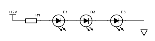
My chromebook uses 19VDC @ 2.31A so I looked at eBay for a boost converter, this is because car voltage is only 12VDC it needs to be stepped up. The chromebook may run from 12VDC directly it probably won’t charge. I got a 3 female Cigarette lighter socket from a hamfest and add 3-green LED in series with a 240-ohm resistors and put them close to the hole in the middle of socket, making the sockets lighted.
Steps
Cut the cord with the end that fits the computer. DO NOT CUT IT TOO SHORT BECAUSE WE WILL USE THAT PIECE TO ATTACH THE BOOST CONVERTER TO THE COMPUTER.
Use your multimeter to find the wire that goes to the tip(Center usually +) and the sleeve(Usually ground). Solder them to the output of boost converter. You may want to attach it to a insulator on copper tape if your going to add a LED.
Connect the LED with the anode(before the arrow on the LED symbol) to resistor and +Vout and cathode(the line, after the arrow symbol) to ground This LED lets you know if its on, wired correctly and has enough juice to power the computer(it will flicker/blink if the computer overloads the boost converter
If you want to light up the cigarette lighter female plug just put them close to hole where the center +12v is. You can wire them in series for multiple jacks, like in the circuit below. The formula for the resistor is $$R_{1}=\frac{12-(V_{F}*n)}{I_{F}}$$ where Vf is the forward voltage drop n is the number of LEDs and If is forward current.
Here are ways to do addition, subtraction, multiply and divide using a multimeter.
Addition
Addition is very simple! To do it just connect some pots in series. With series resistors their resistance adds up.
Subtraction
NOTE: If there are 3 or more pots in series, just set them all the way down to 0 ohms.
Multiply
Again if there are any unused pots set them to 0
Divide
In this animated circuit shows you how the resistors divide the voltage. The resistance isn’t important. You probably want nothing lower than 2.2k(for 32.5v, which is probably the max my adjustable voltage source will give you.) To figure out the current rating use this equation $$I_{max}=\frac{V_{in}}{R}$$ To use that circuit first measure the voltage source output(The numerator of the fraction). Then tap into the resistor chain(the denominator of the fraction). The voltage output from the resistor chain will be the Quotient. You can use any number of fixed resistors and any reasonable value as long is impedance doesn’t go too high where the current is too weak for your meter to pickup. You also don’t want to go too low where your batteries leak or explode or even the resistors could catch on fire if the wattage goes over the rated resistor wattage.
The adjustable voltage source
Here it is. This will give the numerator any number between 1.25 to 32.5. I plan on powering it from 4x 9v batteries. This will provide 36vdc of power. You can use anything from 40v or less. If anything higher is needed you can build a rectifier diode chain, I’m not sure if it’s accuracy is any good. Any adjustable linear voltage regulator is good for this purpose To change the voltage range on the LM317 click here.
This program allows you to wire up a 2-digit Binary clock, Digital clock or both. It uses inpout32.dll file to output the time on the data register. I used a rj45 to db25 male module to make connection to my parallel port and the clock. There are 8 wires (9 if you want the hour and minute indicator). RJ45 has 8-pins so it works.
System Requirements
Windows 2000 or higher (32-bit Windows recommended)
A parallel port that supports the registers (most USB adaptors do not support it, they only support printers)
All programs are virus free. Some antivirus software might say its "suspicious" or a "Potentionaly Unwanted Program". Some of them rate them on what there code looks like no matter if theres a definition in the virus database. If any of them are detected any Antivirus I will zip the software with the password "justin" j is lowercase
pinoutdigital clock interfacewindows xp screenshot
This game is a work of art! The rules are simple, in fact it may even be easier to win than regular solitaire! The object of this game is to discard all the cards by taking a pair of 2 cards and adding them up to 11. Jacks, queens and kings are only discarded when there is only one of each visible they are discarded automatically. It has a Cheat-sheet feature that shows all combinations that can be made. You can either drag and drop cards or type in there number. There number is the # on each card. For example in this screenshot to discard the 7 of clubs and the 4 of clubs type 23. The source code is written in Delphi.
All programs are virus free. Some antivirus software might say its "suspicious" or a "Potentionaly Unwanted Program". Some of them rate them on what there code looks like no matter if theres a definition in the virus database. If any of them are detected any Antivirus I will zip the software with the password "justin" j is lowercase
This is a simple network cord tester that uses just 8 unique resistors. The values/wattage doesn’t matter as long as the meter can read them. They should be in the kiloohm range. I have made an Excel spreadsheet file that you can enter all 8 of the resistors and get the total parallel resistance. The pins are listed as binary 1s and 0s. J1 and J2 are the RJ45 connectors. I even entered the ones I’m using. It doesn’t tell you if it’s a patch cord, crossover or rollover, but tells you if the pins used on the cord are making connection. To tell what type of cord it is just look at the 2 ends.
This is a simple signal injector that can fit inside a mini basketball pump it requires:
1x dc blocking capacitor(10nF to 10uF) C3(2.2uF Axiel Film Capacitor)
2x 100nF Capacitors C1 and C2
2x 1k ohm resistors R1 and R2
2x 4.7k ohm resistors R3 and R4
2x General Purpose NPN low power transistors Q1 and Q2(I used PN2222A)
A 1.2 to 14v dc power source
A alligator ground clip
This signal injector can come in handy for repairing radios, amplifers and old TVs and also square wave generator in a probe. Later on I will make a version that uses C1 and C2 as 470nF and R3 and R4 as 1 Megaohm and C3 as 47uF(Since the frequency is ultralow).
The specs
Where R=R2 or R3, C=C1 or C2 and \(C_{3}\)=C3
Frequency: \(f=\frac{1}{1.38RC}=1.5kHz\)
Output AC Resistance: \(X_{C3}=\frac{1}{2\pi*fC_{3}}\)
This contest is to show your christmas decorations you put up this year. There is no prize but its just to show your christmas sprite. Voting ends 12/31/2023 and posting 12/25/2023. Note you can only vote once
This is a simple wire tester all you need is a 12-1000vac non-contact voltage detector. The ideal is to connect AC live wire to the red circle is. You do not use ground or neutral wires, these wires should be cut off. If the cord is shielded(coax) the detector doesn’t. Even though there’s only one wire used you should not touch the wire. The 5v is actually the ac mains voltage. The three switches choose 1 out of 8 outputs to connect the ac live wire to.
Whats needed
1x spdt switch
1x dpdt switch
1x 4pdt switch
1x RJ45 Jack
1x Polarized ac power cord
a project box that is big enough to fit everything
MultiMeter
screwdriver
drill
drill holes in the box for wires and switches
connect all switches as shown in the picture at the top. NOTE THAT THE LAST SWITCH OUTPUTS GO TO THE RJ45 JACK
Next set your multimeter to lowest resistance range and check for continuity between live wire pin and rj45 connector. this will help find the correct pinout on the switches
This tester is pretty simple and cheap to build. All you need is
2x RJ45 Female connectors(like the ones for putting into the wall)
4x 2-pin Bi-color LEDs
4x 150 ohm resistor
USB A Male Connector(I cut a USB Cord)
4x DPST or DPDT Switches
A PCB Or floor tile and copper tape
Some wire.
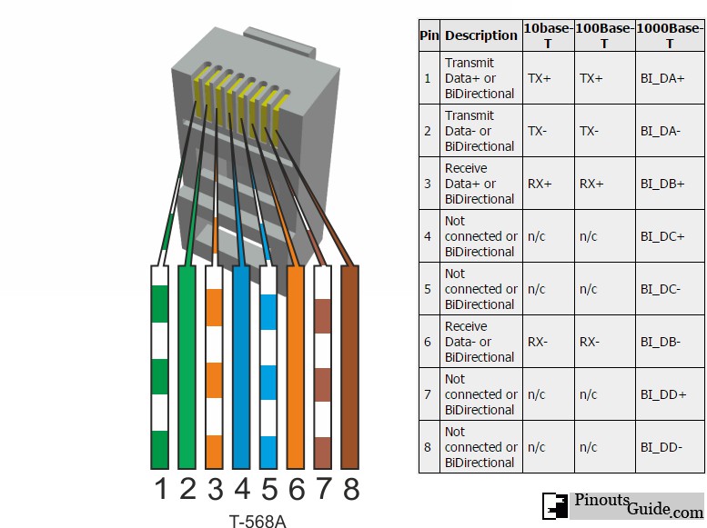
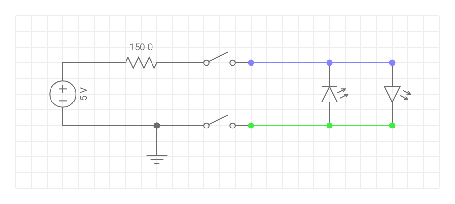
First cut and strip the USB Cord so that red and black wires are available to solder. Solder the white wire of the pair to the negative end of the switch and the solid color goes to the positive end of the switch like shown in the circuit diagram. The red wire will be connected to the resistor and the other end of the resistor is common + for the switches(solid color). The black is the ground for the switch(white wire of the pair). See figure 1 for RJ45 twisted pairs colors, include all 8 pins including the not connected.
Figure 1. RJ45 Pinout(note that it may use 1 and 2 as the orange pair and 3 and 6 as green pair)
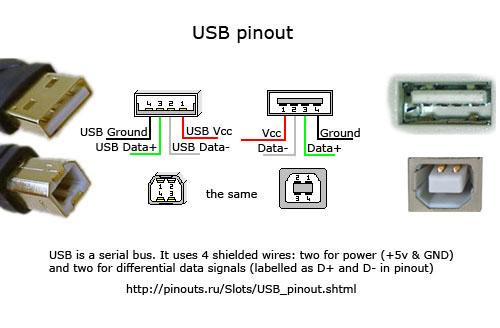
Figure 2. USB Pinout
Figure 3. Per Twisted pair
To use simply turn one switch at a time to test the polarity of the twisted pair. Checkout the table below for test results.
Twisted Pair
Straight-through
Crossover
Rollover
1 and 2
Positive 1 and 2
Positive 3 and 6
Negative 7 and 8
3 and 6
Positive 3 and 6
Positive 1 and 2
Negative 3 and 6
4 and 5
Positive 4 and 5
Positive 7 and 8(1Gbps) or positive 4 and 5
Negative 4 and 5
7 and 8
Positive 7 and 8
Positive 4 and 5(1Gbps) or positive 7 or 8
Negative 1 and 2
Figure 4 LED Polarity Truth Table
The bold results are not needed for 10/100Mbps connection. Of course you could use a arduino,counter chips or flip flops. But that wouldn’t be the simplest tester.
delphijustin Industries is an Autism Supported Business


 Circuit Simulator